
The earliest PCB (printed circuit board) were made from materials like Bakelite, Masonite, layered cardboard and even thin wooden planks. Holes were drilled into the material and then flat brass "wires" were riveted or bolted onto the board. Connections to components were usually made by pressing the end of the brass trace onto a hollow rivet and the component's leads were simply pressed into the open end of the rivet. Occasionally small nuts and bolts were used in place of the rivets. These types of PCBs were used in early tube style radios and gramophones in the 1920's.
In 1956 the US Patent Office issued a patent for the "Process of Assembling Electrical Circuits" that was sought by a small group of scientists represented by the US Army. The patented process involved using a base material like melamine to which a layer of copper foil had been securely laminated. A drawing was made of the wiring pattern and then photographed onto a zinc plate. The plate was used to create a printing plate for an offset printing press. An acid resistant ink was printed onto the copper foil side of the board that was etched to remove the exposed copper leaving the "printed wire" behind. Other methods like using stencils, screening, hand printing and rubber stamping were also proposed to deposit the ink pattern. Holes were then punched in patterns using dies to match the position of the component wire leads or terminals. The leads were inserted through the non-plated holes in the laminate material and then the card was dipped or floated on a bath of molten solder. The solder would coat the traces as well as connecting the leads of the components to the traces.
Much has changed since then. With the advance of plating processes that allowed hole walls to be plated came the first double sided boards. Surface mount technology, something we associate with the 1980's was actually being explored twenty years earlier in the 60's. Eventually the inks were being screen printed onto the panels before assembling the boards. Areas that were meant to be soldered were blocked out on the screens. It helped keep the boards clean, reduce corrosion and oxidation but the tin/lead coating used to coat the traces would melt during the soldering process causing the mask to flake off. Because of the wide spacing of the traces it was seen more as a cosmetic problem than a functional issue. By the 1970's circuitry and spacing was becoming smaller and smaller and the tin/lead coating that was still being used to coat the traces on the boards began fusing traces together during the soldering process.
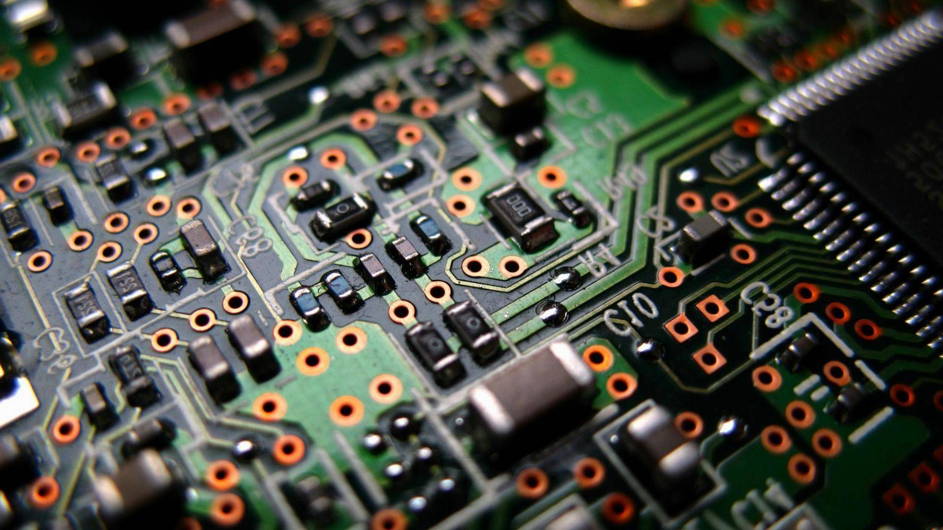
Hot air soldering methods began in the late 70's allowing the tin/lead to be stripped after etching eliminating the problem. Solder mask could then be applied over the bare copper circuits and leave only the plated holes and pads free to be coated with solder. As holes continued to get smaller and trace work became more densely packed solder mask bleed and registration issues brought on dry film masks. They were primarily used in the US while the first photo-imageable masks were being developed in Europe and Japan. In Europe the solvent based "Probimer" ink was applied by curtain coating the entire panel. The Japanese centered on screen processes using various aqueous developed LPIs. All of three of these mask types used standard UV exposure units and photo tools to define the pattern on the panel. By the mid 1990's the aqueous developed liquid photo-imageable masks were dominating the industry with specialized equipment designed specifically for their application.
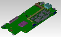
The increased complexities and densities that were driving the evolution of solder mask were also forcing the development of layers of copper traces laminated between layers of dielectric materials. 1961 marked the first use of multi-layer pcbs in the United States. The development of the transistor and the miniaturization of other components drew more and more manufacturers into using printed circuit boards for an increasing number of consumer products. Aerospace equipment, flight instrumentation, computers and telecommunication products as well as defense systems and weapons all began to take advantage of the space saving that a multi-layer circuit board provided. Surface mount devices were being designed that wers wilenth the size and weight of the comparable through hole components. Followed by the invention of integrated circuits the circuit board has continued to shrink in almost every way. Rigid boards and cable applications have given way to flexible circuit boards or combinations of rigid and flexible PCBs. These and other advancements will keep the manufacture of PCB a dynamic field for many years.
Tag: PCBA, EMS, OEM, PCB assembly, ECM, OEM,Prosoyo
.jpg)